Objective

BioNode is a wrist-worn health wearable that doubles as an autonomous emergency beacon. Day to day it works as a continuous health monitor, tracking ECG/EMG, blood-oxygen and heart rate (PPG/SpO₂), electrodermal activity (EDA), body temperature, and motion through a multi-modal analog front end built around a high-resolution biopotential AFE. In a crisis, it fuses those same signals to automatically detect a medical anomaly such as a cardiac event or a fall, determine the wearer's location, and transmit an alert even with no cellular coverage. This suits people who are both at health risk and frequently off-grid: lone workers, hikers, rural patients, and expedition or rescue teams. Its differentiator as a beacon is doing all three at once - automatic, self-locating, and infrastructure-free. Location and comms come from three co-located radios - BLE, GNSS, and a dual-band LoRa transceiver spanning terrestrial sub-GHz and S-band direct-to-satellite, each with its own engineered RF front end and time-multiplexed to prevent interference, so the alert gets out whether or not a ground network is in range. The whole system is integrated into a compact 30×30 mm two-board mixed-signal stack, a 6-layer sensor PCB and an 8-layer Main PCB.

Key Features:

Analog & Mixed-Signal Front End

  • 24-bit delta-sigma ADC with biopotential AFE (ADS1292) integrated with bottom-layer exposed ENIG dry electrodes for 2-channel ECG/EMG acquisition.

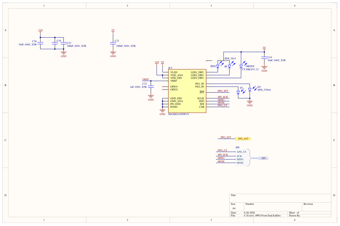
  • A discrete SpO₂/HR analog front end, Maxim MAX86141, for pulse oximetry and heart rate.

  • A dedicated bioimpedance AFE (Maxim MAX30001) for bipolar EDA/GSR acquisition, sharing the EMG electrodes through a low-leakage precision analog MUX (MUX509) in a two-state scheme — on-demand biopotential (ECG/EMG) and background EDA.

  • High-precision body temperature sensing (TMP117) with a dedicated skin-side thermal path, isolated from internal heat sources.

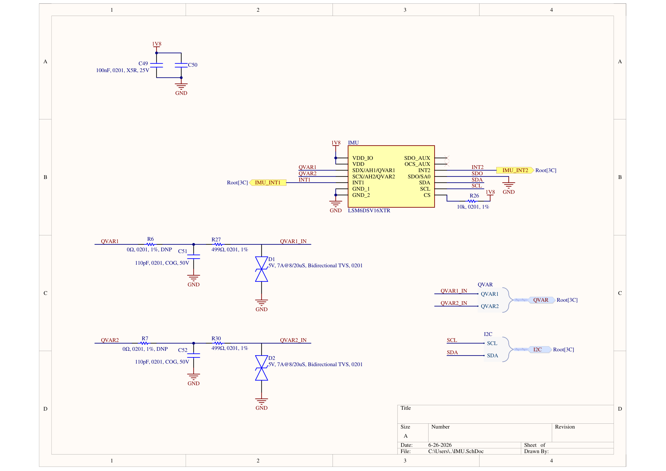
  • The IMU tracks the patient's exact physical movement in real-time, allowing the MCU to mathematically subtract motion-induced noise from the sensitive ECG and SpO₂ signals while providing info on the user's physical state like waking, running, resting, etc.

RF & Connectivity

  • A three-radio architecture with engineered RF front ends — 2.4GHz BLE (nRF54L10), L1-band GNSS (u-blox MAX-M10S) for location, and a dual-band LoRa transceiver (Semtech LR1121) for terrestrial sub-GHz and S-band direct-to-satellite communication — enabling the device to act as an autonomous emergency health beacon that transmits the patient's location even with no cellular coverage.

  • Each antenna has a dedicated front end with a BPF SAW filter and LC matching; the GNSS receive chain adds an external LNA, and the LR1121 satellite path uses a TCXO for frequency stability.

  • RF coexistence is managed through per-band SAW filtering, corner antenna placement for maximum isolation, and a single-radio-active-at-a-time state machine to prevent self-interference between the co-located radios.

Filtering

  • High CMRR (100dB+) biopotential AFE to reject common mode noise

  • Digital Notch filter to remove 60Hz AC hum

  • Hardware LPF with common mode cut-off frequency of 19.74KHz and a differential cut-off of 9.87KHz on ECG electrodes to filter RF noise

  • Digital LPF of 40 Hz cut-off frequency to remove EMG noise in ECG signals

  • Active RLD (Right Leg Drive) and low PGA (To prevent saturation) to remove dry electrode DC offset and Common mode noise from ECG

  • Multi-stage ESD and defibrillation protection on all electrode inputs (referenced to IEC 60601-2-27), with filtering on the side-mounted ECG target electrode matched to its ECG channel partner to preserve CMRR

Power Management

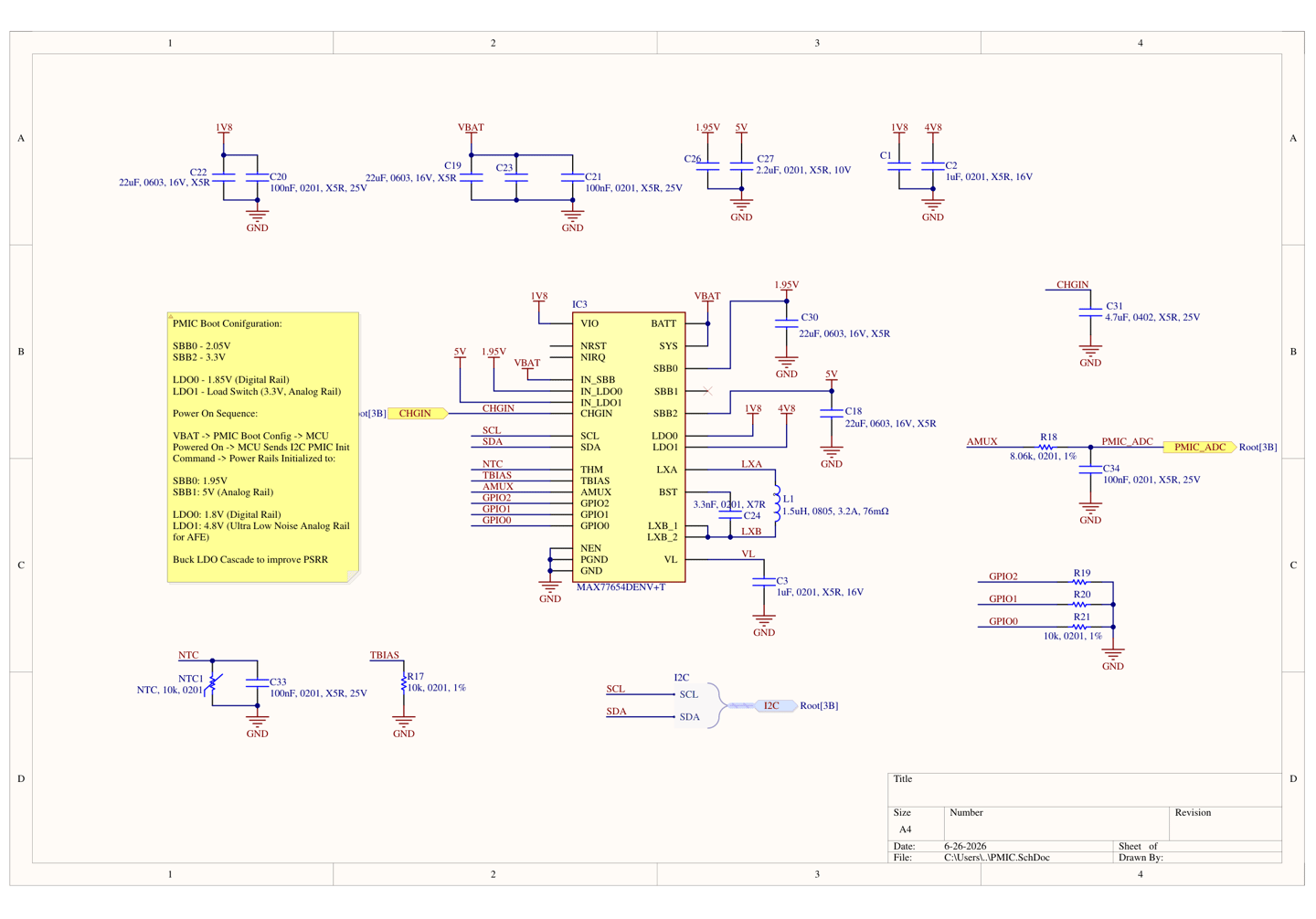
  • A high-end PMIC specifically designed for wearables - Maxim MAX77654 SIMO PMIC

  • Specifications of PMIC are a 1S LiPo BMS and charger, 2 buck rails, 1 boost rail and 1 ultra-low noise LDO

  • Buck-LDO cascade for biopotential AFE for stable and low noise power rail

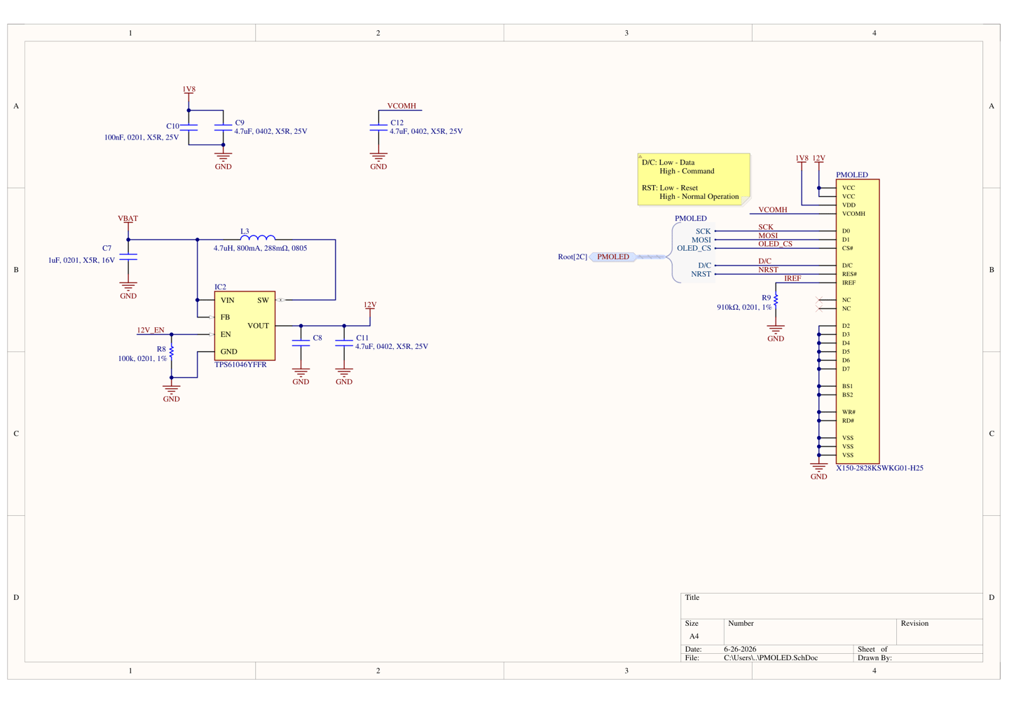
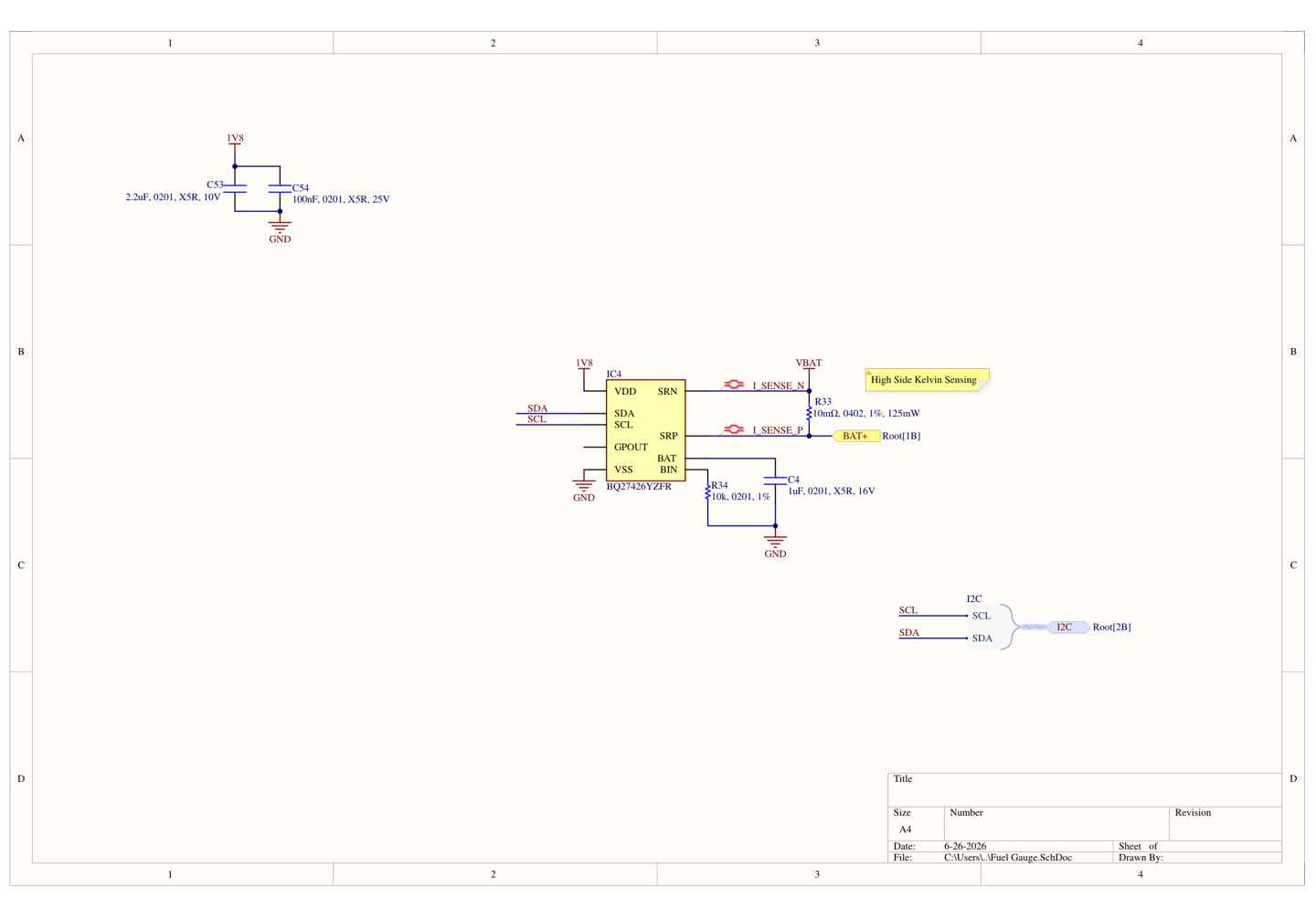
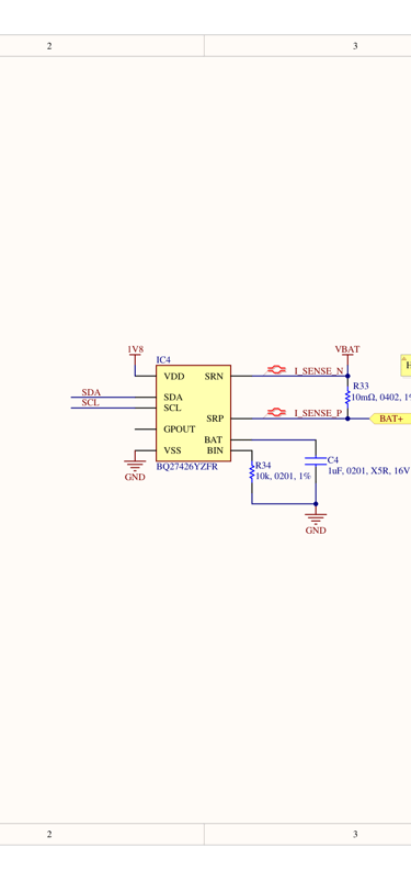
  • A separate PMOLED boost rail (TPS61040) for the 1.3" COG display, with battery fuel gauging (BQ27426) and a 4-pin magnetic pogo-pin charging connector

  • Under-voltage lockout (2.8V) to protect the 1S LiPo from over-discharge

Architecture & Interfaces

  • A two-board stack — a 6-layer analog/sensing board and an 8-layer digital/RF board — joined by a board-to-board mezzanine connector carrying the SPI/I²C buses and the power rails, physically separating the sensitive biopotential front end from the noisy radios and power converters.

  • On-board QSPI NOR flash (512 Mbit) for data logging, and a 1.3" COG PMOLED for status and alerts.

  • Native UART on the charging pogo-pins for a wired console, with SWD test points for debug/programming, and BLE OTA for field firmware updates.

PCB Design

  • Targeting 30mm * 30 mm high-density PCBs — 6-layer sensor board and 8-layer main board

  • Using packages like BGA, LGA, QFN, etc. as much as possible for space efficiency.

  • Using small sizes like 0201 for passives

  • Stackup target - At least two internal GND planes, GND pours on rest of the layers, one power plane and three SIG layers

  • Noise reduction techniques such as via shielding, proper return path tracking and physical isolation of Analog/Digital/Power/RF sections